Elliott Deyell — Year 2, Applied Science
Abstract
Despite their common use in introductory science demonstrations, bottle rockets are rarely used to investigate advanced physics and engineering concepts. This study examined how varying the throat diameter of a converging-diverging rocket nozzle affects water rocket performance. Using Autodesk Fusion 360, three attachable nozzles were designed and 3D printed for testing. The entrance diameter, exit diameter, and nozzle height were kept constant to isolate the throat diameter as the primary variable. Throat diameters of 5mm, 6.5mm, and 8mm were tested alongside a control rocket without a nozzle. Acceleration data were collected using a Micro:bit accelerometer attached to each rocket during launch. The results suggested that larger throat sizes increased instability, while smaller throat sizes restricted flow and reduced thrust efficiency. Of the designs tested, the 6.5mm nozzle produced the best balance between stability and thrust. These findings indicate that nozzle throat diameter significantly influences rocket performance and demonstrate how bottle rockets can model the engineering trade-offs present in real aerospace propulsion systems.
Introduction
Since time immemorial, humans have been drawn to the stars. Ancient civilizations created myths around constellations they saw in the sky and used them to navigate. Over the centuries, attempts were made at flight, leading to the conception of rocketry. The first rocket engine was created over 100 years ago, and various pioneers have brought the technology to where it is today (Cerantola, 2007). Some of the most notable figures in the development of rocketry include Konstantin Tsiolkovsky, Robert Goddard, Hermann Oberth, and Werner Von Braun. Tsiolkovsky was a Russian engineer who presented the mathematical foundation for space flight, including identifying exhaust velocity as an important performance factor. One of the first to design and test rockets, Robert Goddard launched the first liquid-propellant rocket in 1926, realizing the benefits of thrust chamber cooling and turbo pumps. Oberth contributed a great amount to the field, from introducing the parachute, realizing flight velocity, and formulating equations for isentropic flow through nozzles (Cerantola, 2007). Finally, Von Braun developed the first large-scale liquid-propellant rocket, the V-2, while part of the German army. Through operation paperclip, he and other German scientists immigrated to the United States, working on both the Redstone rocket as well as the Saturn V, the first and only rocket to bring humans to the moon (National Aeronautics and Space Administration, 2024). Without these ingenious people, humanity would never have been able to go to space, launch telescopes, and land on the moon.
While Tsiolkovsky, Oberth, and others created the mathematics behind rockets, the basic principles that underly rocketry are conventional. Rockets operate off of one of the fundamental concepts in physics, Newton’s Third Law of Motion, which states that for every action, there is an equal and opposite reaction. The propellant in a rocket is what’s being pushed out, causing and opposite force propelling the rocket upwards, following Newton’s Law. As explained by Patil et al. (2022), the nozzle is the device found at the end of the rocket which is used to channel the propellant to provide thrust.
To understand the impact of the nozzle, it is imperative to understand the basics of the rocket. There are four forces that the rocket is subjected to during flight: weight, thrust, lift and drag. Lift and drag are dependent on atmospheric properties and act through the centre of pressure. The weight, however, is determined by the mass of the rocket, while the thrust depends on the mass flow rate through the engine and the velocity of the propellant through the exit of the nozzle. (Ogale et al., 2016) For the thrust to overcome the weight, a certain impulse is required, meaning a high amount of thrust over a short amount of time. The amount of impulse needed can be calculated, and helps to determine the necessary propellant, which then determines the nozzle design. Choosing an efficient nozzle design is critical, as the nozzle determines the mass flow rate, the exit velocity, and the pressure at the exit of the engine, all of which determine the amount of thrust produced.
The most common nozzle shape is the converging-diverging nozzle, however, the bell-shaped nozzle and conical nozzle are also used (Cerantola, 2007). Early nozzle designs were axisymetrical conical or bell-shaped, which often exhibit under and over expansion due to the fixed outlet area ratio. Underexpansion occurs when the pressure at the exit of the nozzle is greater than atmospheric pressure, while overexpansion is the opposite (Cerantola, 2007). Carl de Laval introduced the Converging-Diverging nozzle in 1882, which has demonstrated the highest exhaust velocities as it maximizes the area expansion ratio. The nozzle is initially converging, pinched at the centre, also known as the throat, before diverging outwards (Harikrishnan et al., 2021). For this nozzle shape, the exit edge radius and angle of narrowing down are important factors to consider, along with the exit diameter. Overall, these different types of nozzles vary in efficiency in different conditions, but the Converging-Diverging nozzle is the most widely used in modern rocketry.
Having briefly introduced the fundamental principles of rocketry, it is evident that the field is both extensive and highly complex, which can make early rocketry lessons challenging for educators to deliver. Most people, whether in science class, on a field trip, or even at summer camp, have made bottle rockets. They are simple in design, consisting of a 2L bottle, a nose cone, fins, and a nozzle, but they are the perfect way to demonstrate the basic physics behind modern rockets.
When trying to understand fundamental laws of physics, students are often told to memorize equations and concepts out of context. Demonstrations, such as bottle rockets, benefit students by providing them with a practical example to relate the theory to. Concepts such as, inertia, gravity, acceleration, air resistance, Newton’s Laws, work and energy, impulse and momentum, and more are all applicable to bottle rockets. While these concepts may seem difficult to grasp, when students are able to relate back to a real example, comprehension is much easier (Correa et al., 2025).
How, then, do bottle rockets operate? In the absence of conventional engines or combustion processes, the mechanism responsible for propelling a soda bottle into the air may not be immediately apparent. Bottle rockets nonetheless rely on Newton’s Third Law, similar to modern rocket systems; however, they utilize water as the reaction mass. Pathan et al. (2016) explain that as air is pumped into the rocket body, it is compressed, becoming a pressurized gas, which pushes on the water. This force is met with a reactionary force from the water, causing the rocket to shoot up into the air when released. Given the area of the nozzle and the inner and outer pressures, the mass flow rate of the bottle rocket can be calculated, eventually allowing the calculation of the rocket’s acceleration. With only a bottle, water, and a pump, a range of fundamental physics concepts and governing equations can be effectively applied, enabling the construction of a reasonably accurate simulation of a rocket system.
While bottle rockets are used in classrooms across the globe thanks to their simple design and low cost, they are often kept in their simplest form. Specifically, a bottle with a nose cone and fins. However, these devices have much more potential, both scientifically and for educational purposes. Numerous studies have examined the design and performance of full-scale rocket nozzles; however, upon reviewing this literature in the context of this paper, it became apparent that much of it is highly technical and challenging to interpret at the secondary-school level, despite a strong background in physics. As such, in this experiment, the impact of different throat sizes in a converging–diverging nozzle on the acceleration of a bottle rocket will be investigated. This exercise can be replicated by other high school students, providing an entry-level understanding of rocketry and nozzle technology. Further, not many of the studies reviewed for this paper systematically investigated how variations within a single nozzle geometry affect performance. While some compared different nozzle types, others focused on modified designs, leaving a gap in controlled studies on parameters such as throat size. This experiment will serve as add to the knowledge on this subject, albeit with a simpler vehicle than a true rocket.
Materials and Methods
Nozzle Design
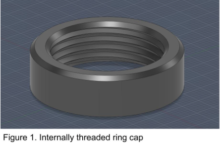
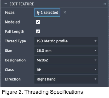
Designing a working attachment for the nozzles to the 2L plastic pop bottles was the first step taken in this experiment. Using Autodesk Fusion, a 35mm in diameter, 3.372mm wide, and 9mm high internally threaded ring cap was designed and 3D printed (Figure 1). At first, the threaded ring did not properly attach to the 2L bottles, so adjustments were made to the threading designation. The final specifications for the threading can be seen in Figure 2.
Next, the conical diverging-converging nozzle shapes were designed to attach to the previously designed threaded ring. The dimensions of the nozzles can be seen in Figure 3. Three designs were created with varying throat radii of 5mm, 6.5mm, and 8mm, which required angle modification. The total height was kept to be a uniform 77.94mm, as well as the entrance and exit diameters which were held at 14mm and 18mm respectively, in order to isolate throat size as a variable.

3D Printing Specifications
Once the designs were finalized, all of the nozzles were printed using a Bambu Lab X1 Carbon printer. A cool plate was used, with generic black PLA filament from AMZ3D and a layer height of 0.2mm, on the 0.20mm Standard @BBL X1C process setting. The third nozzle was printed with a green PLA filament.
Stand Design
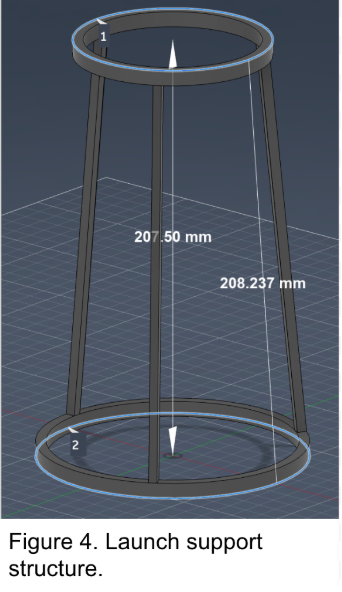
With all of the nozzles printed and functional, the support structure for launching the rockets was designed, once again using Autodesk Fusion. The structure consisted of two rings, with 42.50mm and 60mm radii, respectively. The two rings were connected by three supports, making the total structure 207.5mm tall (Figure 4). The structure’s purpose was to hold the rocket level while being pumped.
General Rocket Set-Up
Next, small holes were drilled through approximately the centre of three sizes of Paulin Taper Cork, each corresponding to the different nozzle diameters. After initial tests, the junction between the nozzle and the 2L bottle was not airtight. To counteract this, washer tape was added between the bottle and nozzle, then Gorilla Epoxy Adhesive was added overtop and allowed to dry.
A V2 Micro:bit encoded to record acceleration data was then attached to the outside of the rocket, using duct tape, along with its power supply. The rockets were then filled with 600 mL of water via a measuring cup. The needle of a ball pump nozzle, attached to a bike pump, was pushed through the drilled holes in the cork, which was then put in the throat of the nozzle. Then, the rockets were placed on the support structure, and inflated to until the cork was blown out. The launches were then recorded with an
Figure 5. Nozzle attached to 2L bottle iPhone 13’s camera. Each nozzle was tested once, along with a control lacking a nozzle, as fractures appeared in the 3D structure due to the high pressures.
Results
The V2 Micro:bits recorded acceleration data in mg’s in the x, y, and z axes. They were removed from the rocket after the launches were complete and the data was downloaded off of them. The total acceleration was then calculated from the full data. Then, based on the recordings, the section of the data including the launch was selected and turned into a graph, as shown below.
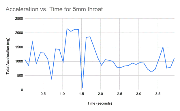
Figure 6: The proper acceleration versus time graph for the 5mm throat nozzle.

Figure 7: The proper acceleration versus time graph for the 6.5mm throat nozzle.
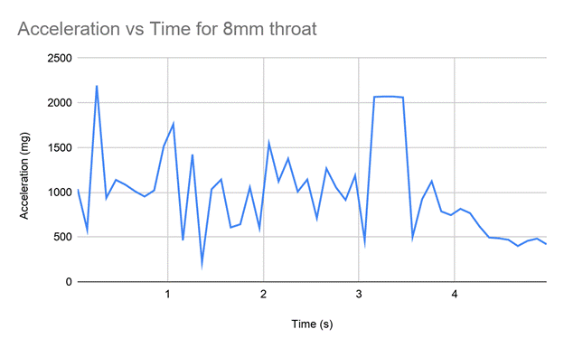
Figure 8: The proper acceleration versus time graph for the 8mm throat nozzle.

Figure 9: The proper acceleration versus time graph for the control, with about an 11mm diameter.
In an ideal scenario, the acceleration of the bottle rocket would resemble the following. Initially, the proper acceleration is 1000 mg (or 1g) as it sits on the platform, with no net force acting upon it. This is because the accelerometer measures proper acceleration rather than acceleration relative to the ground. While stationary, the launch platform exerts an upward normal force equal to the downward force of gravity, causing the accelerometer to register approximately 1g despite the rocket not moving. Once the air pressure has built up and overcomes the friction force holding the cork in the nozzle, the acceleration will increase rapidly. The acceleration is determined by the thrust force and the mass of the rocket, according to Newton’s second law: F = ma (Benson, 2021). Thrust force is determined by the equation Fthrust = mve, where ve is the escape velocity of the water. Benson (2021) demonstrates how these two equations are rearranged to a = (Fthrust – Fg) / m. This equation explains the added complexity of a rocket’s mass decreasing as fuel is propelled out, increasing acceleration if Fthrust remains constant. The behaviour expected of water rockets based on these equations is an initial peak of acceleration, then a steady decrease back to 1000 mg when all of the water has been expelled. Once all of the water is expelled, the net force is solely the force of gravity, so proper acceleration remains constant at 1000 mg.
Analyzing the graph of acceleration for the water rocket with a 5mm nozzle throat (Figure 6), while the general shape follows the ideal scenario, there are some deviations from expectation. The launch and largest Fthrust occurs right after 1.0s, reaching a maximum 2120 mg, before decreasing back to around 1000mg at 2.0s. However, rather than a smooth decline in acceleration, the decrease is punctuated by a large drop. In practice, it is very rare for thrust to be smooth, and such fluctuations as the one observed here may be explained by the sloshing of water in the bottle, the turbulent mixing of airflow and water, and rotation. Additionally, cavitation may have contributed to these fluctuations, as rapid pressure changes near the nozzle throat can cause small vapour bubbles to form and collapse within the water flow. These factors can decrease the ability of the water to flow smoothly out of the nozzle, causing deviances in the acceleration data.
Figure 7 represents the acceleration data for the water rocket with a 6.5mm nozzle throat. The acceleration is consistently 1000mg until launch just before 1.0s. At about 1.1s, the acceleration reaches its maximum, as would be expected. The decay afterwards is smooth, with fewer extreme spikes than the 5mm nozzle throat, but there is one noticeable dip. Flow instability may be an explanation for this dip, as it lasts for a fraction of a second before acceleration resumes. This instability may also have been influenced by brief cavitation within the nozzle as pressure rapidly decreased during expulsion
The graph of acceleration for the bottle rocket with the 8mm nozzle throat (Figure 8) is noticeably different from the previous trials. While the maximum acceleration of 2193 mg is reached just after 0.0s, the decrease in acceleration is not smooth, showing a lot of noise. There are various peaks over the following seconds, with a noticeably high peak at 3.1s. The larger diameter of the nozzle can likely account for the variation and noise observed in this graph. A larger diameter allows water to exit faster, delivering the thrust over a shorter amount of time, resulting in a more forceful and less stable expulsion. The nature of this higher thrust can cause stronger turbulence, more wobble, and orientation changes that can affect accelerometer data.
One bottle rocket was launched without a nozzle, allowing water to exit out of the standard, 11mm diameter hole. Figure 9 depicts the results of this trial, once again following the expected shape, with some differences. There is a very short thrust phase, with the maximum acceleration reaching 2987 mg at 1.3s, a much higher peak than the other trials. The acceleration decreases quickly, punctuated by a few spikes due to normal flow instability, before returning to 1000 mg at 2.1s. Due to the speed at which the water is expelled, there is less time for the oscillatory behaviour observed in Figure 8 to appear. However, the extremely rapid flow rate may also increase the likelihood of cavitation occurring near the bottle opening, further contributing to unstable flow behaviour. It is important to note that the height achieved by this trial was significantly lower than the others, indicating that despite the high thrust, the overall impulse may not have been as significant.
Discussion
When comparing all four trials, the following general patterns were observed. The 5mm nozzle demonstrated restricted but relatively controlled flow, with a single dip interrupting the decrease in acceleration. The 6.5mm nozzle represented the best balance of thrust and stability, with the smoothest decay of acceleration out of all of the trials. The 8mm nozzle displayed significant noise, indicating behaviours of increased instability and sideways motion, confirmed by visual recordings. Finally, the 11mm control exhibited an extremely rapid pressure loss with a short impulse, resulting in a lower maximum height, but large initial thrust.
From these patterns, there seems to be an optimal diameter to maximize both the maximum acceleration reached, and the smoothness of the thrust. Too large of a throat can drop pressure at a rapid pace as well as shorten the thrust duration, leading to the destabilization of the rocket. On the other hand, a small throat has smoother thrust, but a much more restricted flow. The 6.5mm, mid-size, rocket nozzle seemed to balance the thrust while remaining relatively stable.
There remain a few sources of error in the experimental design of this project that are important to consider. Primarily, after the launch of each nozzle, fractures in the 3D layers of the nozzles themselves were observed. The high pressure within the bottle right before launch caused these fractures, and rendered them unusable for multiple trials. As such, each throat size was only tested once, allowing for random error and variability. In the future, a stronger material than PLA should be used to create the nozzles to ensure pressure is only escaping through the throat.
The second significant error observed was the instability of the launching stand. Due to the pressures involved in launch, after two trials the stand cracked, resulting in a less level platform for the rockets to launch from. The angle at which the rocket is launched in vitally important, as that determines the direction the thrust force will act on the rocket and thus the direction of flight. The positioning of the bottles could have been further offset by the force that came with inflating them through the bike pump. Had a stronger material been used for the stand, and slower, less forceful inflation been conducted, these errors could be minimized.
Moreover, a further consideration for this project would be the inclusion of a cylindrical nozzle with a throat of 11mm to serve as a control. By maintaining the same nozzle height while removing the converging–diverging geometry, the investigation could more directly isolate the effects of nozzle shape on thrust generation, exhaust velocity, and overall flight performance. Comparing the cylindrical nozzle to the optimized designs would also help determine whether the observed performance gains were due to throat diameter or to the expansion profile of the nozzle itself.
Additionally, a possible source of experimental error was the attachment of the accelerometer system to the rocket body. The micro:bit and its external battery pack were taped to opposite sides of the bottle using duct tape in an attempt to balance the mass distribution. However, the masses of the two components were not identical, meaning the rocket’s centre of mass could have been unevenly distributed. This imbalance may have caused an increase in sideways motion or rotational instability during flight, particularly in trials that already exhibited noise within the acceleration data. Further, the positioning and attachment method of the components may have influenced the direction of the thrust force relative to the rocket’s centre of gravity, affecting both the stability and accuracy of the recorded acceleration measurements. In future investigations, a more symmetrical mounting system should be used to ensure a balanced mass distribution and reduce unintended rotational effects during launch.
Conclusion
Overall, the results of this investigation indicate that nozzle throat size could have an impact on the acceleration and stability of a bottle rocket. While the control trial produced the greatest peak acceleration, it may have expelled water too quickly, resulting in a short thrust duration and lower overall flight height. Conversely, the 5mm nozzle restricted flow and limited thrust, while the 8mm nozzle introduced substantial instability and inconsistent acceleration due to rapid water expulsion. Of the designs tested, the 6.5mm converging–diverging nozzle produced the most balanced performance, generating strong acceleration while maintaining a relatively smooth thrust curve. These findings support the idea that rocket nozzle design is not solely about maximizing force, but rather optimizing the relationship between thrust magnitude, thrust duration, and flight stability. Even within the simplified context of water rockets, the same engineering trade-offs faced in full-scale aerospace design become apparent.
This investigation also highlights the educational value of bottle rockets as a tool for teaching complex physics and engineering concepts in a more accessible manner. Through the design, testing, and analysis of custom nozzles, principles such as Newton’s Laws, impulse, fluid dynamics, and rocket propulsion were explored in a practical setting that extends beyond traditional classroom learning. Although limitations such as material failure, inconsistent launch conditions, and limited trials affected the precision of the experiment, the project successfully demonstrated how small design modifications can meaningfully alter rocket performance. Future investigations could build upon these findings by testing stronger materials, conducting repeated trials, and further isolating variables related to nozzle geometry. Ultimately, this experiment reinforces the idea that even simple bottle rockets can serve as valuable models for understanding the principles that continue to drive modern space exploration.
References
Barnhart, P. J. (1997). NPAC – Nozzle Performance Analysis Code. National Aeronautics and Space Administration. https://ntrs.nasa.gov/api/citations/19970024876/downloads/19970024876.pdf
Benson, T. (2021). Rocket Principles. National Aeronautics and Space Administration.
https://www.grc.nasa.gov/www/k-12/rocket/TRCRocket/rocket_principles.html
Cerantola, D. J. (2007). Rocket Nozzle Design with Ejector Effect Potential [Master’s Thesis, Carleton University]. Carleton University Research Virtual Environment. https://carleton.ca/atarg/wp-content/uploads/Thesis_DC_Final.pdf
Correa, R. G. A., & Rafaela, H. T. (2025). The Construction of PET bottle rockets with water propulsion were means used to develop a Meaningful Learning of Newton’s Third Law in a High School class. Journal of Physics, Conference Series, 2950. https://doi.org/10.1088/1742-6596/2950/1/012015.
Harikrishnan, R., & Lokavarapu, B. R. (2021). Design and analysis of rocket nozzle. Materialstoday: Proceedings, 38(5), 3365–3371.https://doi.org/10.1016/j.matpr.2020.10.370
Holland, C. (2005). Analysis of a water-propelled rocket [Master’s Thesis, University of Leeds].
National Aeronautics and Space Administration. (2024, February 6). Wernher Von Braun. NASA. https://www.nasa.gov/people/wernher-von-braun/
Ogale, A., Marathe, O., Misal, S., & Anekar, N. (2016). Design of Nozzle and Fin Locking Unit for MRECM Rocket: A Study. International Journal of Current Engineering and Technology, 4, 347-351. https://doi.org/10.14741/Ijcet/22774106/spl.4.2016.69
Pathan, R. R., Dheepak, A., & Tijare, S. (2016). Design and Development of Water Rocket. International Journal of Innovation in Engineering, Research and Technology, 11, 1-5. https://www.neliti.com/publications/426709/design-and-development-of-water-rocket
Patil, P., Birajdar, A., Kuwar, D., Naigaonkar, R., Madhavi, V., Gaikwad, V., & Kothmire, P. (2022). CFD Analysis of Different Shape Rocket Nozzles. Fluid Mechanics and Fluid Power, 3, 427-439. https://doi.org/10.1007/978-981-99-6343-0_33