Oliver Guo — Year 2, Applied Science
Abstract
Roadside flagging places workers close to moving vehicles and remains a safety concern in construction zones. Automated Flagger Assistance Devices (AFADS) reduce exposure, but prior work suggests that cost, setup difficulty, and deployment constraints still limit their use. This project aimed to design a compact prototype flagger unit that could support future AI based automation while integrating local computation abilities, traffic message display, and remote control. A prototype was assembled using a Raspberry Pi 5, a 64 × 64 RGB LED panel, a USB webcam, and a custom 3D printed PLA enclosure mounted on a tripod. Current testing verified that the camera could be accessed by the Raspberry Pi, the LED panel could display traffic control messages, and display changes could be sent from a second, remote, Raspberry Pi through MQTT.
Introduction
During government construction projects, roads and lane segments often need to be sectioned off, requiring temporary traffic control to maintain flow while work is performed. This role is typically carried out by human workers, referred to here as flaggers, who guide vehicles at close range. This working environment presents significant risks. Drivers may be distracted, speeding, impaired, or unfamiliar with temporary traffic patterns, increasing the likelihood of collisions or close calls within construction zones.
As a result, flagging remains one of the more dangerous roadside jobs in North America. Reporting by the Canadian Broadcasting Corporation, citing WorkplaceBC data, recorded 15 fatalities and hundreds of injuries involving roadside workers in British Columbia between 2007 and 2017, with roughly half involving traffic control personnel. In the United States, 54 flagger fatalities were reported between 1980 and 1992, all involving workers struck by vehicles in construction zones (Ore, 1997).
The hazards of the job are inherent, as no amount of training received by a flagger can prevent traffic incidents stemming from poor driver behaviours. Instead, reducing the need for humans to work in a potentially dangerous position by substituting with technological alternatives seems like an opportunity worth investing in.
Automated flagger assistance devices (AFADs) are one of the technological alternatives available and were developed to reduce the exposure of flaggers to traffic. AFADs allow an operator to remotely control these devices to display a “stop” or “slow” with a variety of methods – usually a combination of a changeable message sign, red and orange lights, and movable arms to blockade cars from entering work zones (Cottrell, 2006).
An evaluation conducted in Missouri found that AFAD deployments reduced direct worker exposure to traffic and produced consistent driver responses comparable to those with human flaggers, and later surveys with participants indicated that 78.05% of them preferred an AFAD to human flaggers. (Brown et al., 2016).
Although AFADs can improve worker safety and maintain decent traffic control in shared lane scenarios, their effectiveness relies strongly on site layout, setup time, and equipment placement (Finley, 2013). It is noted that complications regarding deployment limited the use of AFADs, especially in shorter projects or more constrained construction zones.
Despite their safety benefits, AFADs are observed to not be used regularly due to their inefficient deployment and reduced cost-effectiveness. Specifically, some larger systems are challenging to maneuver in construction spaces, especially in urban settings, compared to a human flagger. In terms of cost, AFADs still require a worker to control the system and the cost of an AFAD system itself, which can reach $25k USD per unit (Cottrell, 2006). These cost premiums may be a factor to why flaggers are used more often than AFADs.
Han and Zhu (2022) proposed a fully automated, vision-based flagging system for construction zones as an alternative to both human flaggers and AFADs. Their system used cameras and a specialized YOLOv5-based object detection model to monitor traffic and support simple control decisions. In their prototype, four cameras were mounted on a single stand near the work zone and streamed video to a computer, which detected and tracked vehicles and then displayed either “stop” or “slow” on an LED panel. The cameras, computing hardware, display, and power supply were integrated into a self-contained unit capable of operating without internet access (Han and Zhu, 2022). The system’s decision module applied basic rules based on vehicle position and movement to determine which signal should be shown. In lab-based testing with simulated traffic conditions, the prototype was able to respond to detected vehicle movements by displaying the appropriate traffic message. This work showed that vision-based automated flagging is feasible. However, the precision and recall values indicate a significant portion of vehicles were not well detected, and it is shown that detection reliability was unequal across different vehicle types (Han and Zhu, 2022).
Shared lane scenarios pose the highest risk for automated flagging systems. Vehicles approaching from opposing directions must alternate passage through a single conflict zone, unlike non-shared lane scenarios, where traffic streams are separated. Once a vehicle is released allowed to drive into a shared lane, conflicts cannot be easily corrected, and bad directions from automated flagging systems can result in safety hazards and traffic delays. Consequently, shared lane scenarios must prioritize the accuracy of decisions (Federal Highway Administration, 2017). In the system proposed by Han and Zhu in 2022, the decision to let vehicles through is determined by detected vehicle presence. In the detection performance from Han and Zhu’s system, a substantial percentage of vehicles are missed, and performance varies by vehicle class. This reliance on detected vehicle presence makes shared lane scenarios particularly sensitive to perception errors.
Existing research, especially that of Han and Zhu, provides evidence of the feasibility and possible implementations of vision-based automatic flagger systems. However, this study does not address how such systems might be deployed in actual shared lane construction zones. The prototype designed by Han and Zhu is implemented as a single centralized unit housing all observing cameras and display panels. Simply put, this design is not suitable for construction zone implementation, as it doesn’t account for longer shared lane distances, varied road layouts, temporary obstructions, and the best angles to optimize sightlines.
Current studies do not fully address how automated flagging systems could be physically deployed in real shared lane scenarios, where road layout, sightlines, and temporary obstructions can affect system reliability. This project focuses on the deployment aspect of the problem by developing a compact and lower costing prototype that can be used for future deployment testing.
Materials and Methods:
General Setup
The prototype was designed as a single unit that could support future vision-based flagger logic while currently functioning as a controllable stop/slow display.
A Raspberry Pi 5 (Raspberry Pi Ltd.) was used as the computing unit; another Raspberry Pi 5 was set up to demonstrate remote control capabilities. Visual output was provided by a 64×64 RGB LED panel with a compatible controller board (T4 series controller, Shanghai Listen Vision Technology Inc.). Power was supplied by a 5V10A, AC to DC power adapter (Model: Dx050v5-01, Shenzhen Yishida Power Technology Col, Ltd.). Camera input was provided by a Dell monitor integrated webcam module (Dell Inc.).
These components were first tested individually, then tested while assembled together to verify system integration. An enclosure was designed in Autodesk Fusion (Figure 1 and 2) and 3D printed in PLA to house every component, measuring 20.8cm wide, 13.5cm thick, and 25.8cm tall. The enclosure was designed to present the LED panel at the front (Figure 3) while housing the Pi 5, panel controller, power adapter, and wiring in the back (Figure 4). A vent was designed into the bottom of the casing to ensure the Pi 5 would not run too hot. The enclosure was then mounted on an adjustable phone tripod (height from 67.5cm to 153.5cm).
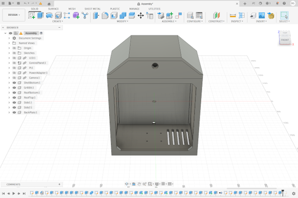
Figure 1: Top and Front View of Enclosure in Fusion360
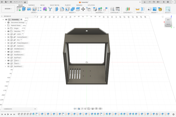
Figure 2: Top and Back View of Enclosure Without Top and Back Covers in Fusion360

Figure 3: Front View of Built Enclosure
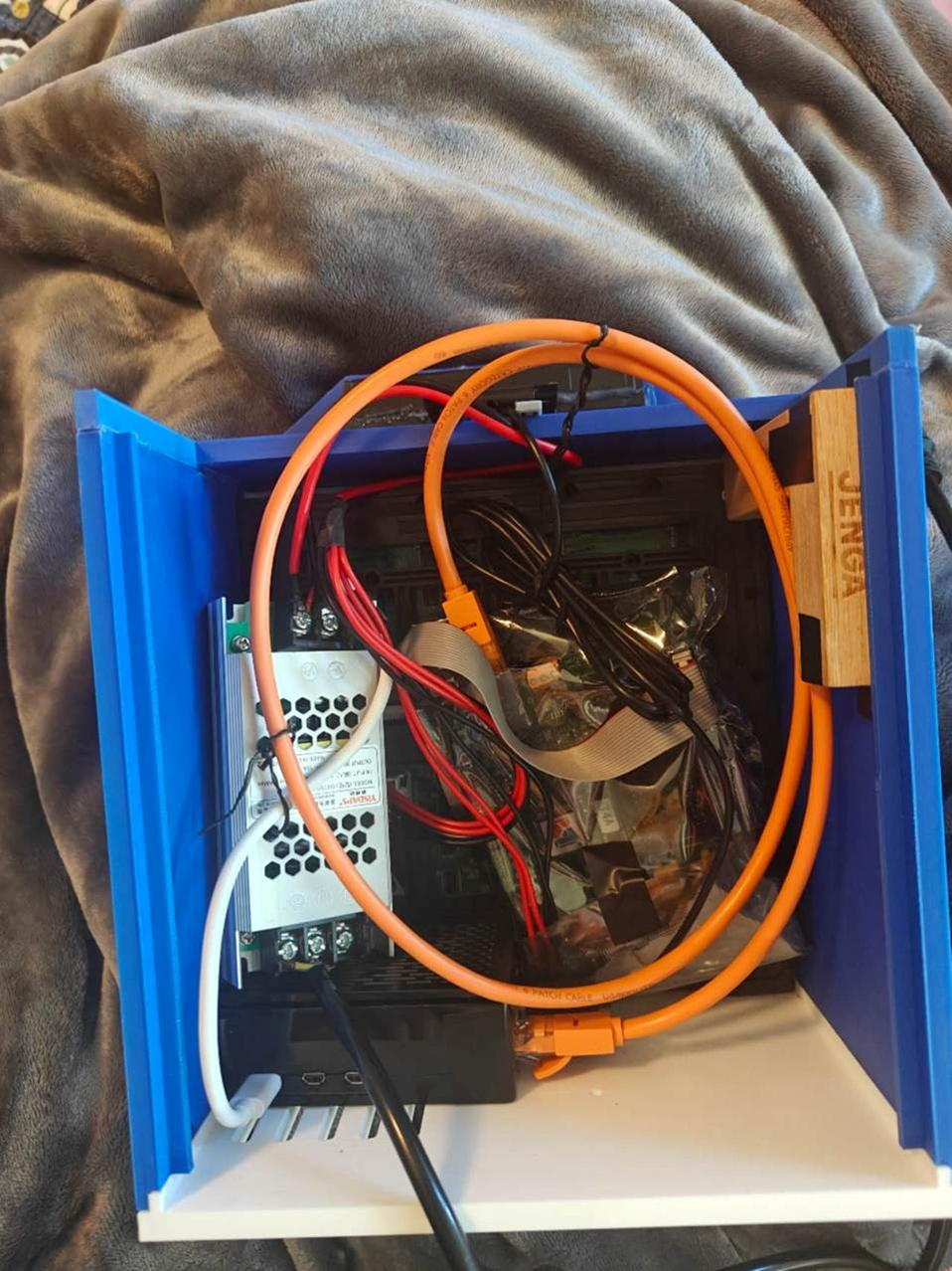
Figure 4: Rear View of Built Enclosure Including Electrical Components
Print Settings
The enclosure was printed using a Bambu Lab A1 printer. The print settings used includes a 0.4mm nozzle, 0.20mm layer height, 2 wall loops, 12% gyroid sparse infill, 3 top and bottom shell layers, monotonic top and bottom surface patterns, and rectilinear infill for internal solid regions. An estimated total of 572.96g of filament was used for the entire enclosure.
Control Panel
The Pi 5 was installed inside the casing and connected to the LED panel and webcam. A demo program to display “Stop” and “Slow” directions to drivers, as well as other text-based messages, on the LED panel was written in python using the library and documentation provided along with the control board (Shanghai Listen Vision Technology Inc.) attached to the controller board. Then the program was adjusted to run on Raspberry Pi’s OS.
Testing
For remote-control testing, the second Pi was connected to the same phone hotspot. A Python script on the external Pi published MQTT commands, while a receiver script on the Pi inside the enclosure listened for commands and executed the display change.
The unit was tested after final assembly. Testing focused on four functions, successful enclosure of all components, camera accessibility from the onboard Pi, control of the LED panel from the onboard Pi, and remote control of the LED panel from the second Pi. A thermal test was performed to compare Raspberry Pi 5 CPU temperature with the board inside and outside of the enclosure. The ambient room temperature was approximately 20°C, and the room was largely stagnant during testing. For each condition, the Raspberry Pi 5 was placed under load for 15 minutes using the Linux stress utility, which was used to load all four CPU cores for the duration of the test. CPU temperature was recorded every 5 seconds. The Pi was allowed to return to its starting temperature before each test so that the runs could be compared under similar conditions.
Results:
Table 1 shows the results of the tests completed.
Table 1: Test Results
| Test | Expected Outcome | Outcome |
| Assembly | Prototype assembled into an enclosed tripod mounted unit | Mostly successful, warping issues on the top cover lead to slight gaps (Figure 5) |
| Camera Access | Webcam access from the onboard Pi | Successful |
| Local Display Control | Onboard Pi able to control LED panel to show preset “Stop” and “Slow” displays | Successful |
| Remote Display Control | External Pi able to communicate with onboard Pi to change preset displays | Successful |
The automated flagging unit was successfully assembled with an enclosure mounted to a tripod mounted. The front face fit the 64 × 64 LED panel, while the rear compartment housed the Raspberry Pi 5, power supply, controller, and wirings. The overall arrangement matched the intended design. The printed shell was suitable for assembly and testing, although slight warping and alignment issues during printing have caused defects on the top cover, causing minor fitting issues.

Figure 5: Misprints on the Top Cover
The onboard Raspberry Pi successfully accessed the webcam module during testing. The LED panel also successfully displayed programmed traffic messages, including “Stop” and “Slow,” when controlled locally from the onboard Raspberry Pi.
Remote control was also demonstrated. When the external Pi sent commands to the onboard Pi, the displayed message on the LED panel changed accordingly.
The Raspberry Pi 5 temperature increased steadily during both thermal tests and then began to level off during the middle of the trials (Figure 6). The trials in and out of the enclosure show very similar results and growth, with both reaching low to mid 80°C range under sustained load.
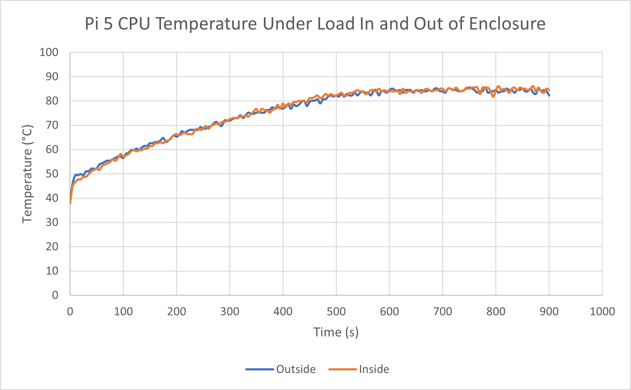
Figure 6: Pi CPU Temperature Under Load
Discussion
The prototype was successfully assembled into a single unit, and its core functions like camera access, local panel control, and remote panel control, were demonstrated.
Within the context of existing flagger technology, this project focuses on ease of deployment and attempting cost efficient design. Prior AFAD studies have shown safety benefits yet also noted limitations in cost, layout, and deployment complexity (Brown et al., 2018; Finley, 2013; Cottrell, 2006). Han and Zhu (2022) demonstrated that camera-based automated flagging is feasible, but their entire system was assembled as one unit and does not fully address how such systems should be packaged or positioned in actual work zones.
The current prototype addresses these limitations by integrating the camera, processor unit, and display into a compact tripod mounted unit using relatively inexpensive components compared to hiring a flagger.
Testing showed that the system demonstrated easy deployment as a single device and the ability to be positioned and adjusted nimbly. The remote-control functionality also expands potential for two or more of these units working autonomously together to manage a work zone, or be controlled by an operator remotely. Although the prototype was not tested against existing AFAD systems, the results show that it can function as a compact and adjustable platform for future automated flagger development.
Limitations
However, several limitations remain. First, the prototype enclosure was printed in PLA and is not ready for weather exposure, impacts, or long-term outdoor use. Due to the casing being printed in parts, some joints suffer from tolerance and fit related issues, and were not designed to be weatherproof. Second, due to budgeting limits, the tripod used is likely too flimsy and weak to be implemented in a real system. Furthermore, the prototype uses a cord to draw power; a power cord connected to AC power may not be possible in many scenarios.
Although the camera can be accessed, AI based vehicle detection and traffic control logic were not implemented in the current build. These would allow the system to automatically respond to vehicles and function as more than a remotely controlled or timed display.
The current wireless setup used a phone hotspot to connect the two Raspberry Pis. While this was useful for testing, it does not reflect real world conditions. Finally, the prototype was not evaluated for conditions involving outdoor visibility, camera sightlines, or potential obstructions.
Future Works
If more work is to be done on this project, there are a few directions to focus on. First, AI detection of vehicles and decision logic could be integrated so that the prototype can function autonomously while responding to site conditions. To achieve this, a second unit would need to be built or simulated. A suitable AI detection model would need to be found or trained with regards to limited computation power inside the unit – likely a modified YOLO computer vision model.
Secondly, the prototype could switch to being battery powered instead of relying on a power cord, although the longevity of battery life would be dependent on the size of the battery bank that can fit the enclosure. To help compensate, a mini solar panel could be mounted to the unit to prolong battery life.
Thermal testing was also inconclusive. The Raspberry Pi 5 reached similar temperatures both inside and outside the enclosure during the thermal test at similar speeds, thus the test did not clearly show whether the enclosure affected cooling. However, both tests reached relatively high temperatures under load, so future designs should improve ventilation or include fans to support longer operation.
Finally, a better enclosure could be designed. The current prototype suffers from minor joint tolerance issues, as well as the joints not being designed to be weatherproof. A revised design could include tighter tolerances, more mounting points, and better alignment between the top cover and main body. The new enclosure could also be printed in PETG, which offers higher degrees of temperature and UV tolerance, as well as impact resistance compared to PLA. A sturdier tripod should be attached to the new case to ensure stability, in the case of weather events such as wind, snow, or hail. With the new case, more tests for weather events could be conducted.
Conclusion
This project created a prototype designed to support future automated flagger development. The Raspberry Pi, LED panel, camera, power supply, and enclosure were successfully combined into a single unit, and testing confirmed that camera access, local display control, and remote display control all worked as intended. While minor defects in the enclosure were observed and the system is not yet fully autonomous or ready for field deployment, these results demonstrate that a functional hardware platform has been established for further testing and refinement.
References:
Ore, T., & Fosbroke, D. E. (1997). Motor vehicle fatalities in the United States construction industry. Accident Analysis & Prevention, 29(5), 613–626. https://doi.org/10.1016/s0001-4575(97)00013-4
Brown, H., Sun, C., Zhang, S., & Qing, Z. (2018). Evaluation of automated flagger assistance devices. Missouri Department of Transportation. https://rosap.ntl.bts.gov/view/dot/35103
Finley, M. D. (2013). Field evaluation of automated flagger assistance devices in work zones on two-lane roads. Transportation Research Record: Journal of the Transportation Research Board, 2337, 1–8. https://doi.org/10.3141/2337-01
Cottrell, B. H., Jr. (2006). Evaluation of the AutoFlagger in Virginia (Report No. FHWA/VTRC 07-R12). Virginia Transportation Research Council. https://vtrc.virginia.gov/media/vtrc/vtrc-pdf/vtrc-pdf/07-r12.pdf
Han, W., & Zhu, Z. (2022). Vision-based automated flagging system in construction. In Proceedings of the 1st Future of Construction Workshop at the IEEE International Conference on Robotics and Automation (ICRA 2022). IEEE. https://doi.org/10.22260/icra2022/0004